
TM 5-6115-271-14
TO 35C2-3-386-1
TM 05926A-14
NAVFAC P-8-613-14
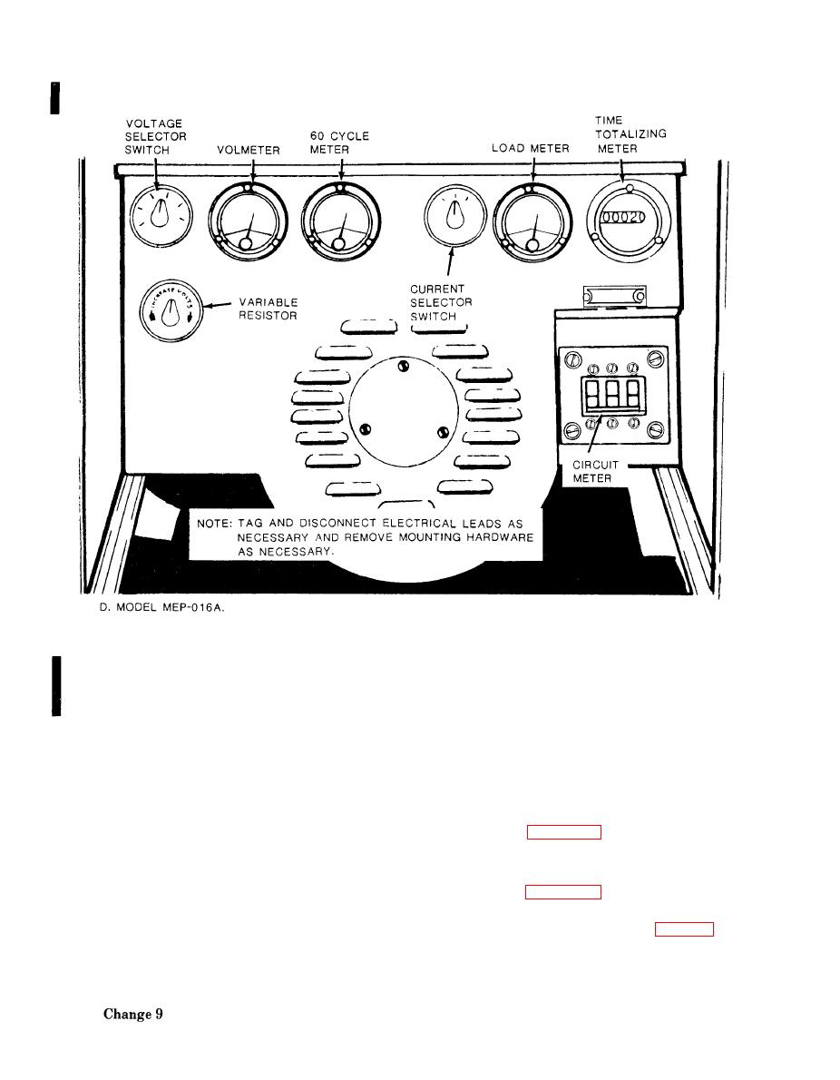
Figure 4-13. Controls and instruments, removal and installation (Model MEP-016A) (Sheet 3 of 3).
reading will be in DC micro amperes. Reading at
minimum deflection at full scale valve will be 0 to 200
in the ON position. Observe reading on set load meter.
micro amperes. Normal reading to 60 Hz or 400 Hz
Meters should indicate according to load attached,
will be 90 to 110 micro amperes.
i.e., 750 watts--25%, 1500 watts--50%, etc.
(c) If reading is not within specifications, stop
(c) If load meter does not read within specifica-
tions, replace the load meter.
accuracy in series with the set frequency meter. Be
b. Removal.
sure to observe polarity.
(1) Open or remove the control box cover (para
(d) Restart the generator set and compare the
4-15).
reading on the set meter and test meter. Frequency
(2) Refer to figure 4-13 to remove any of the
variation between these two meters should not exceed
meters as required.
1%.
c. Installation.
(e) If frequency variation exceeds 1% of full
valve, replace the frequency meter.
(1) Refer to figure 4-13 to install any of the
meters as required.
(3) L o a d M e t e r .
(2) Install the control box cover (para 4-15).
and
(a) Connect a load of known wattage
proper voltage to the output terminals of
the
generator set. Maximum load is 3000 watts.
