
TM 5-6115-271-14
TO 35C2-3-386-1
TM-05926A-14
NAVFAC P-8-613-14
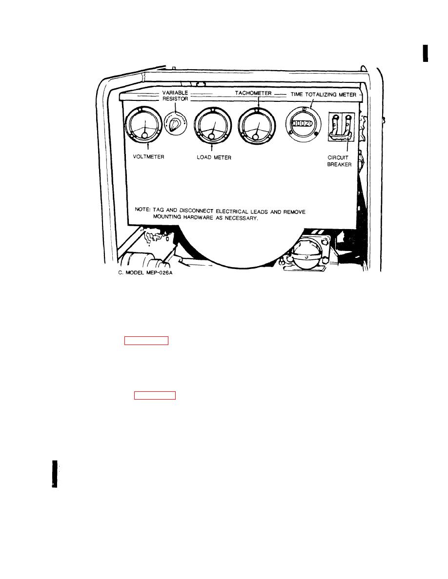
Figure 4-13. Controls and instruments removal and installation (Model MEP-026A) (Sheet 2 of 3).
Figure 4-13. Controls and instruments removal and installation (Model MEP-026A) (Sheet 2 of 3).
(a) Remove load cables from load terminals
(3) If the reading is not within specifications,
and start the generator set.
replace the variable resistor.
(b) Position circuit breaker switch to ON
c. Removal. Using figure 4-13 as a guide, remove
position.
the variable resistor as follows:
(1) Tag and disconnect all electrical leads.
across load terminals on all position settings of the
(2) Remove mounting hardware as necessary.
voltage selector switch. Output voltage should not
(3) Remove the variable resistor.
vary more than 5% from the set voltmeter.
d. Installation. Using figure 4-13 as a guide, install
(d) If voltage varies more than 5%, replace the
the variable resistor as follows:
voltmeter.
(1) Replace the variable resistor.
NOTE
All meters (except the voltmeter)
(2) Install mounting hardware.
suspected of malfunction should be tested
(3) Connect all electrical leads and remove the
by comparison with calibrated master in-
tags.
struments at Direct Support Level or
4-17. Frequency Meters (400 Hertz and 60 Hertz),
equivalent.
Voltmeter, Loadmeter, and Tachometer (MEP-026A,
(2) Frequency Meter.
MEP-026C Only).
a. Test.
set.
(1) Voltmeter.
across the terminals of the frequency meter. This
4-19
Change 9
