TM 5-6115-271-14
TO 35C2-3-386-1
TM-05926A-14
NAVFAC P-8-613-14
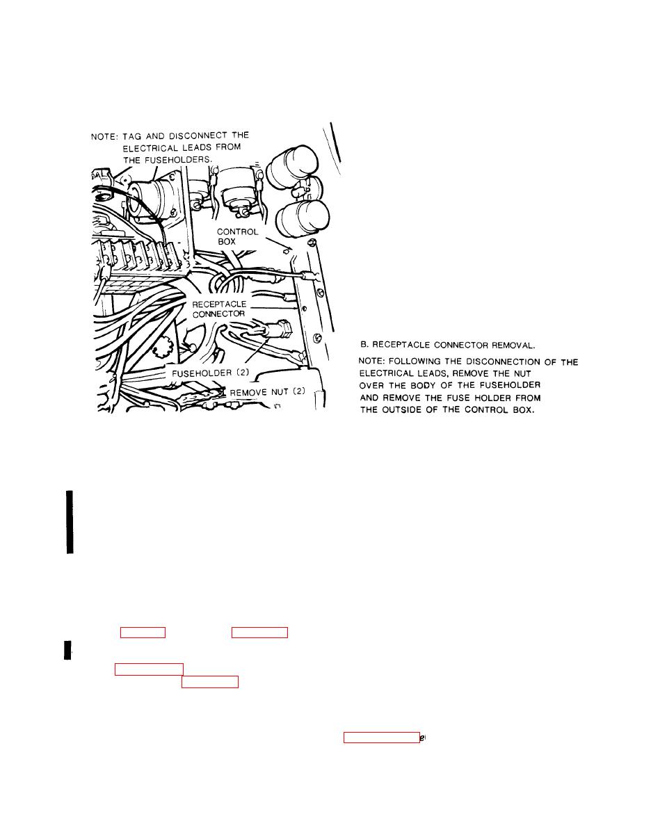
(2) Remove the nut over the body of the
fuseholder and remove the fuseholder from the out-
NOTE
side of the control box.
Double check that correct meter is being in-
b. Installation.
stalled when it needs replacing. AC hour
meters and DC hour meters are not
(1) From the outside of the control box, replace
interchangeable.
the fuseholder and install the nut over the body of the
fuseholder.
a. Test. Test the time totalizing meter by checking
it against a reliable clock. Check mission duration
(2) Connect all electrical leads and remove the
time against the time totalizing meter.
tags.
b. Removal and Installation. To remove or install
the time totalizing meter, open or remove the control
a. General. Models of the generator set manufac-
box cover (para 4-15) and refer to figure 4-13.
tured prior to 1968 are equipped with a field flash
4-19. Fuseholder (Model MEP-016A, MEP-016C)
switch. This paragraph contains instructions for test,
removal and installation of the switch if the generator
Refer to paragraph 4-15 and open or remove the con-
set is so equipped, and for flashing the generator fields
trol box cover. Refer to figure 4-14 and the following
with or without a field flash switch.
instructions to remove or install the fuseholder.
b. Test. If the field flash switch does not work,
a. Removal.
refer to manual field flashing instructions in
(1) Tag and disconnect the electrical leads from
the fuseholder.
manually, replace the switch.


