TM 5-6115-275-14
NAVFAC P-815-14
TO 35C2-3-452-1
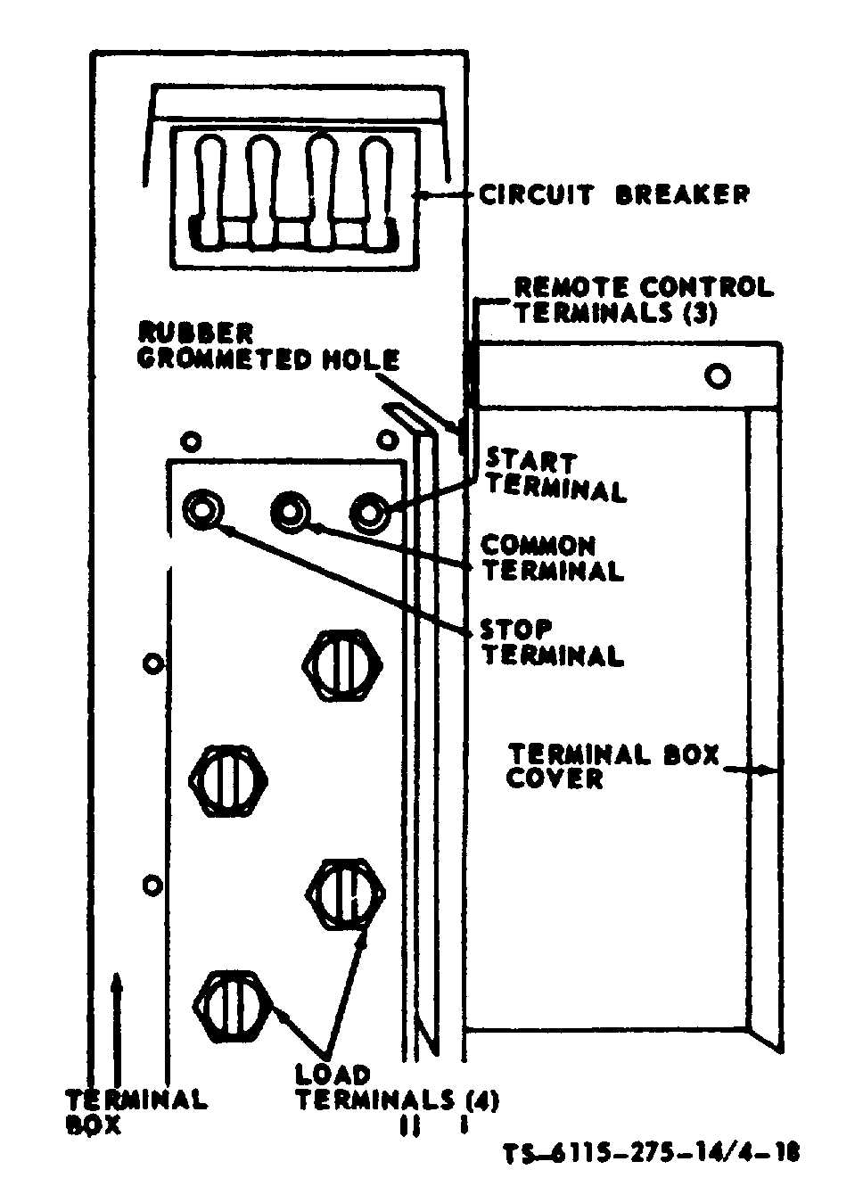
Figure 4-18. Terminal load (Model MEP-023A)
Table 4-1. Output Selector Switch Knob Positions
Knob
Connect load cable
Position
Output
to load terminals
1
240V, 1 phase, 2 wire
L-2 and L-3
*1
120/240V, 1 phase, 3 wire
L-2, L-3, and L-0
2
120V, 1 phase. 2 wire
L-2 and 1.-3
3
120V, 3 phase, 3 wire
L-1. L.2, and L-3
4
120/208V, 3 phase, 4 wire
L-0, L-1, L-2 and L-3
NOTE
No. 1 position is at the extreme left of the travel of the knob. Switch positions 2, 3, and 4 will then be
determined by turning the knob in a counterclockwise direction, the No. 4 position being at the extreme
right of the travel of the knob.
Change 3 4-19