Figure 8-1-Continued.
Figure 8-1
TM 5–6115-323-14
the regulator terminals, the voltage regulator is
defective and should be replaced.
(c) If voltage across regulator terminals 5
and 6 is satisfactory, stop the generator set, at-
tach the load cables, and restart the set.
(d) If voltage is still not satisfactory replace
the voltage regulator and repeat steps (a) thru (d).
(3) Transducer.
(a) Disconnect load cables and start genera-
tor set.
(b) With the multimeter, check output volt-
age across load terminals. Then check input volt-
age across terminals 3 and 4 of the transducer.
These readings should have about the same value
(120 V approximately).
(c) Check input voltage from variable resis-
tor across terminals 1 and 2 of transducer. This
reading will vary but should be approximately 20
v.
(d) Check transducer output to voltage reg-
ulator. Terminals 5 and 6 should be about 120 V.
Terminals 7 and 8 should be about 25 volts.
(e) If output voltages do not meet specifica-
tions, replace voltage transducer.
(4) Capacitor (noise suppression).
NOTE
The only accurate way to test a capacitor is by
putting it on a capacitor testor. However, you can
tell if a capacitor is working by the following
method.
(a) Stop the generator and disconnect the
lead-in terminal to the capacitor.
(b) With the multimeter on ohms setting,
touch test probes to input terminal and capacitor
metal case, then reverse the probes. The multime-
ter will give a momentary reading then fall back
to zero.
the
(c) If this reading does not occur, replace
capacitor.
(5) Frequency converter.
(a) Stop the generator set and disconnect
either the positive or negative lead from the
frequency converter output to the frequency me-
ter.
(b) Start the generator set and measure
input voltage across terminals L1 on the fre-
quency converter with a multimeter. This voltage
will normally be 120 volts AC.
(c) Observing polarity with the multimeter,
measure DC microampher current output on +
and – terminals at the converter. This microam-
pher DC should be within the 0 to 200 microam-
pher range, and at 120 volts, 60 Hz, during opera-
tion this reading should be close to 100 microam-
pher.
(d) If measurements do not meet specifica-
tions above, replace the frequency converter.
(6) Variable resistor (AC).
(a) Stop generator set and disconnect termi-
nal 5 of TB 1 (fig. 1-5).
(b) Insert multimeter probes to this discon-
nected wire and terminal 6 in TB 1 (fig. 1–5). With
the variable resistor in the full counterclockwise
position slowly turn the control knob to the full
clockwise position. This reading should move
smoothly from 0 to 1100 ohms A 20%, as the
variable resistor is rotated to the full clockwise
position.
(c) If the reading is not within specifica-
tions, replace the variable resistor.
8-3. Control Box (DC Unit)
a. Removal and Disassembly.
(1) Remove the control box (para 6-3).
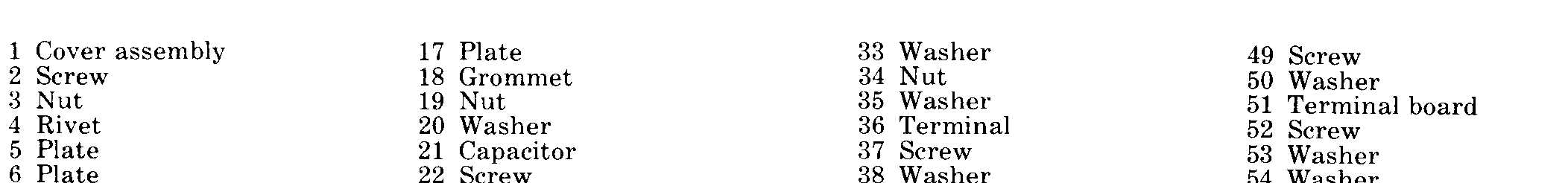
(2) Refer to figure 8-2 and disassemble the
control box.
b. Cleaning and Inspection.
(1) Clean all parts thoroughly.
(2) Inspect all parts for signs of burning or
8–3