TM 5-6115-323-14
TO 35C2-3-385-1
(c) If the reading is not within specifica-
tions, then replace the variable resistor.
8-4. Radio Interference Suppression
a. General. This paragraph contains informa–
tion applicable to the primary suppression compo-
nents that are the responsibility of intermediate
(field), (direct support and general support), and
depot maintenance. For general information on
radio interference suppression, refer to paragraph
4-13. For radio interference suppression informa–
tion that applies to the engines, refer to the
appropriate service manual for engines (See Ap-
pendix A).
b. Interference Suppression Components.
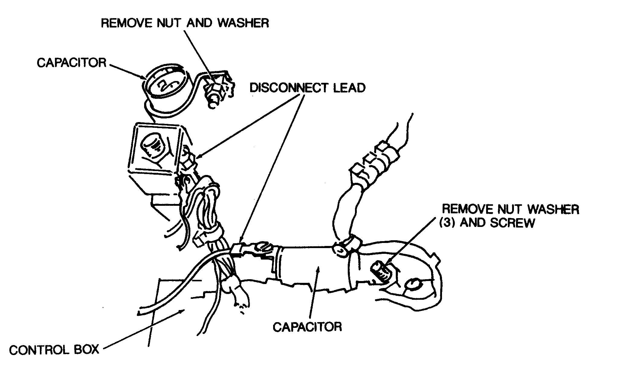
(1) AC Unit. The control box of the AC unit is
equipped with two capacitors that are provided
for interference suppression. They are rated at 0.1
MFD, 500 V, AC/DC. These capacitors are shown
by figure 8-3.
(2) DC Unit. The DC Unit control box is
equipped with two capacitors that provide
suppression of radio interference. They are rated
at 0.5 MFD, 100 V DC. These capacitors are shown
by figure 8-4.
c. Replacement of Suppression Components.
(1) AC Unit. For replacement of interference
. .
suppression components on the AC unit, refer to
figure 8–3.
(2) DC Unit. For replacement of interference
suppression components on the DC unit, refer to
figure 8-4.
d. Testing of Radio Interference Suppression
Components.
NOTE
The only accurate way to test a capacitor is by
putting it on a capacitor tester. However, you can
tell if a capacitor is working by the following
method.
(1) Stop the generator set and disconnect the
lead-in terminal to the capacitor.
(2) With the multimeter on the high scale
ohms setting, touch the test probes to the input
terminal and the capacitor metal case, then re-
verse the probes. The multimeter will give a
momentary reading, then fall back to 0.
Figure 8-3. Radio interference suppression components, removal and installation (AC Unit).
8-6
Change 9