
TM 5-6115-271-14
TO 35C2-3-386-1
TM-05926A-14
NAVFAC P-8-613-14
gases outdoors. Provide metal shields for the exhaust
line if it passes through flammable walls. Wrap the line
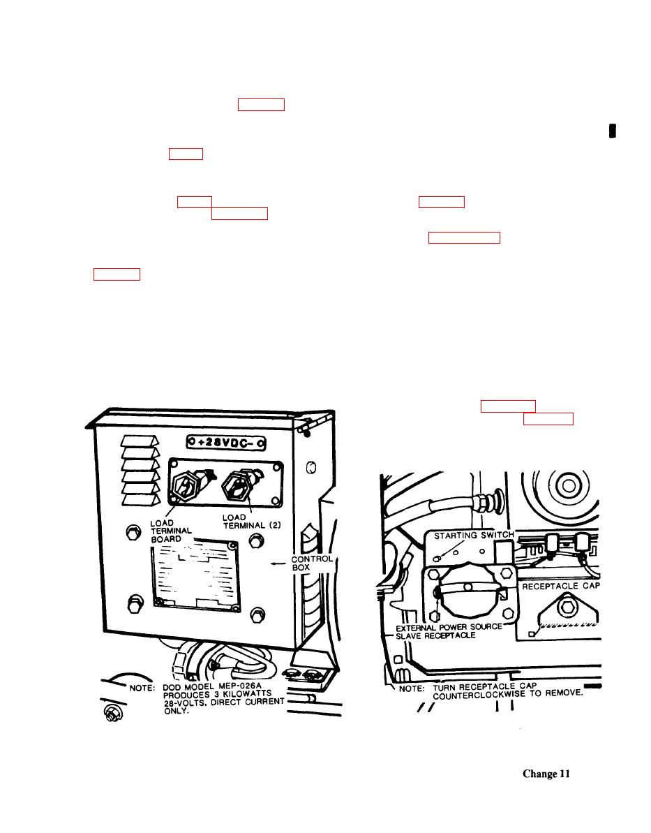
nect the load cables to the DC generator load termi-
with fiberglass if there is any danger of anyone touch-
nals. Relatively light electrical loads (12 amps) maybe
ing the exhaust line.
connected to the generator set by plugging in to the
slave receptacle (fig. 1-3).
4-3. Equipment Conversion (Models MEP-016A,
MEP-016C, and MEP-021A, MEP- 021C)
d. External Fuel Source. If an auxiliary fuel source
is to be used, connect the auxiliary fuel hose to the fuel
selector valve (C, fig. 2-1). A special adapter may be
required for all models (see Appendix B, Section III).
021A/C for voltage and phase desired.
e. External Power Source. When an auxiliary
cables to the proper load terminals.
power source is to be used to start the engine, connect
the external power line to the receptacle illustrated in
4-4. Procedures for Constructing Revetment
NOTE
a. General. This equipment is designed to operate
in the open with unrestricted ventilation. In some situ-
The external power source must be 24/28
ations, it may be necessary to operate the equipment
volt direct current.
from the protection of a revetment. This paragraph
provides information for the construction of a revet-
f. Indoor Installation. Keep the area well venti-
ment to protect the equipment should it become nec-
lated at all times so the generator set will receive a
essary.
maximum supply of air. Install a gas-tight exhaust
line, as large as the exhaust outlet, to pipe the exhaust
b. Dimensions. The minimum allowable inside
dimensions are shown in figures 4-4 and 4-5. The
entrance to the revetment is shown in figure 4-6. These
minimum dimensions are based solely on consider-
ation of engine cooling and ventilation allowing
