TM 5-6115-271-14
TO 35C2-3-386-1
TM-05926A-14
NAVFAC P-8-613-14
(3) Set potentiometer R6 to 250 ohms
e. Adjustment.
(halfway).
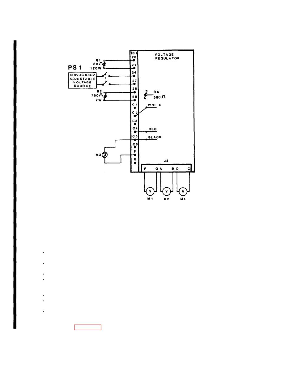
(1) The following components and equip-
(4) Turn AC power supply (PS1) on.
ment are needed for the adjustment procedures on the
voltage regulator.
(5) Slowly increase AC voltage (0 to 30 VAC)
while monitoring DC voltmeter (M1) and oscilloscope
Two DC Voltmeters 0.5 percent,
(M3). DC voltage reading on DC voltmeter (M1) shall
0-100 VDC (M1 and M4)
increase proportionally with the increasing AC voltage
AC Voltmeter 0.5 percent, 0-150
and the voltage wave form trace of oscilloscope (M3)
VAC (M2)
shall move toward a positive voltage level. A voltage
Oscilloscope (M3)
shall also be indicated on DC voltmeter (M4). The
Voltage source 0-150 VAC 60 Hz,
waveform trace of oscilloscope (M3) swinging below
Regulation 0.25 percent, from 0-2
the zero axis (negative) during this (0-30 VAC) test
Amps (PS1)
shall be indicative of an unusable/defective opera-
Resistor 30 ohms, 120 watts (R1)
tional amplifier.
Resistor, 750 ohms 5 percent, 2
watts (R2)
(6) Increase AC voltage for a "maximum
reading" on meter (M1) (35 VDC minimum) or until
Potentiometer, 500 ohms (R6)
oscilloscope (M3) wave form is just starting to come
(2) Connect voltage regulator, equipment,
off the "maximum level" refer to curve 1 of Figure
and components as shown in Figure 8-1 E.
8-1F.
8-4.6
Change 11


