TM 5-6115-332-14
P-8-614-14
TO 35C2-3-424-1
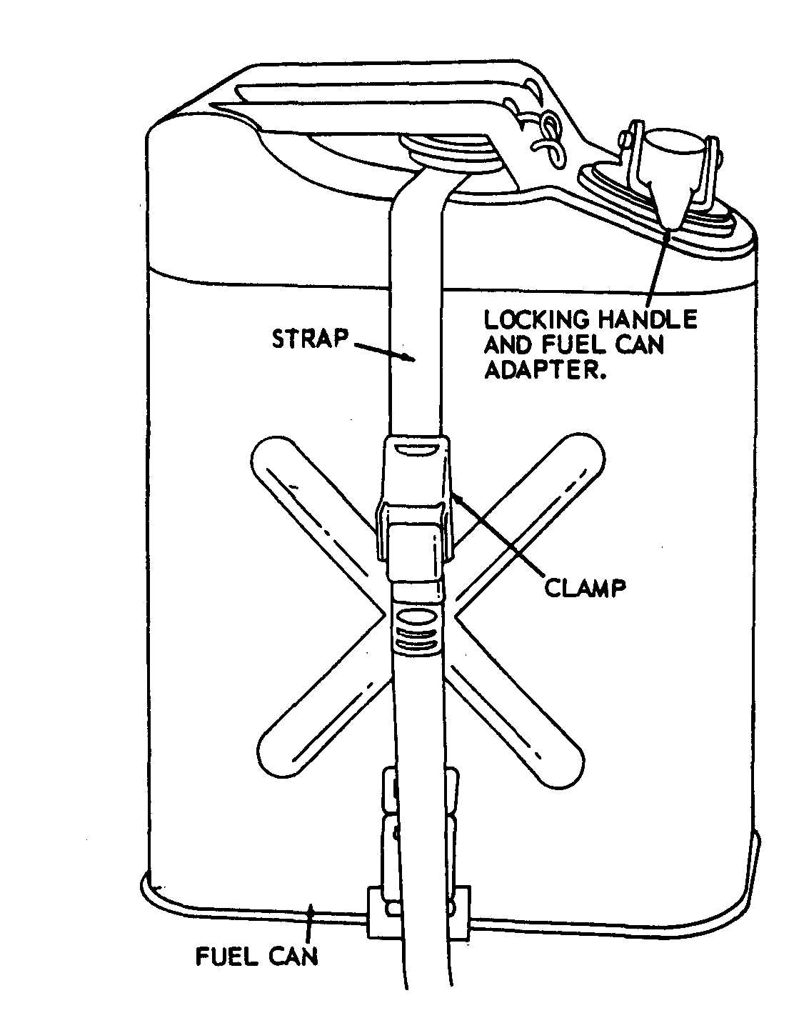
Figure 3-4. Fuel can, removal and installation.
3-12.
Electrical System
a. Inspect the battery cable, hold down frame, starter
cable, and slave receptacle for damage.
b. For replacement, report to organizational
maintenance.
3-13.
Battery
a. Inspection. Inspect battery for cracks and for
proper electrolyte level.
b. Service.
When servicing the battery, do not
smoke or use an open flame in the
vicinity. Batteries generate a highly
explosive gas.
NOTE
The 6TN and 6TL batteries can be mixed or
matched. However, maintenance-free batteries
cannot be mixed or matched with military
batteries. The 6TN and or the 6TL batteries will
perform properly in hot weather as long as
electrolyte levels are carefully monitored. If the
electrolyte expands and causes the level to rise,
some fluid must be removed. If the level becomes
too low due to evaporation, distilled water may be
used to obtain the proper level. A good grade of
drinking water (excluding mineral waters) may be
used if distilled water is not available.
Electrolyte (NSNs 6810-00-249-9354 and
6810-00–843-1640) have a specific gravity of
1.280 and should be used in these batteries. Do
NOT adjust the electrolyte in wet batteries to a
lower specific gravity.
Remove the battery vent caps and fill each cell of the
battery to the proper level with distilled water. The correct
level is 3/8 inch (0.95 cm) above the plates. Install the vent
caps.
c. Utilize slave receptacle to supply external power
for charging batteries and extra cranking power.
3-14. Control Box Assembly
a. Removal.
(1) Open the front of the control box by unlocking
the five fasteners located near the top and at the sides of the
control panel.
(2) For removal of fuse (Model MEP-017A), refer
to figure 3–2.
(3) For removal of the lamps, refer to figure 3-3.
b. CIeaning. Clean the fuses and the lamps with a
clean, lint free cloth.
3-14
Change 8