TM 5-6115-275-14
NAVFAC P-8-615-14
TO 35C2-3-452-1
(2)
Relay K2 is used to stop the
engine. The relay is energized by
the S I stop switch and S5
remotelocal switch. When relay
K2 is energized, relays K3 and K4
are
de-energized,
thereby
removing the battery charger from
the circuit and grounding the
magneto through the normally
closed contacts of relay K4.
(3)
Relay K3 is energized by the
battery charger rectifier through
the normally closed contacts of
K4. and de-energized by low oil
pressure.
(4)
Relay K4 is energized through the
normally closed contacts of relay
K2 and the silicon diode, CRI.
This occurs when start and stop
switch, S1, is activated.
(5)
The relays are identical and
interchangeable.
b.
Removal. Refer to figure 7-1 or 7-2 and
remove the relays and resistors
from
the
applicable
model
generator set.
c.
Cleaning, Inspection, and Repair.
(1)
Clean board and relays with a dry
cloth.
(2)
Inspect board for cracks, defective
soldering or printed circuitry and
varnish deterioration.
(3)
Inspect relays and relay sockets
for
corrosion
and
damage.
Replace damaged items.
d.
Installation. Refer to figure 7-1 or 7-2 and
install the relays and resistors on
the applicable model generator
set.
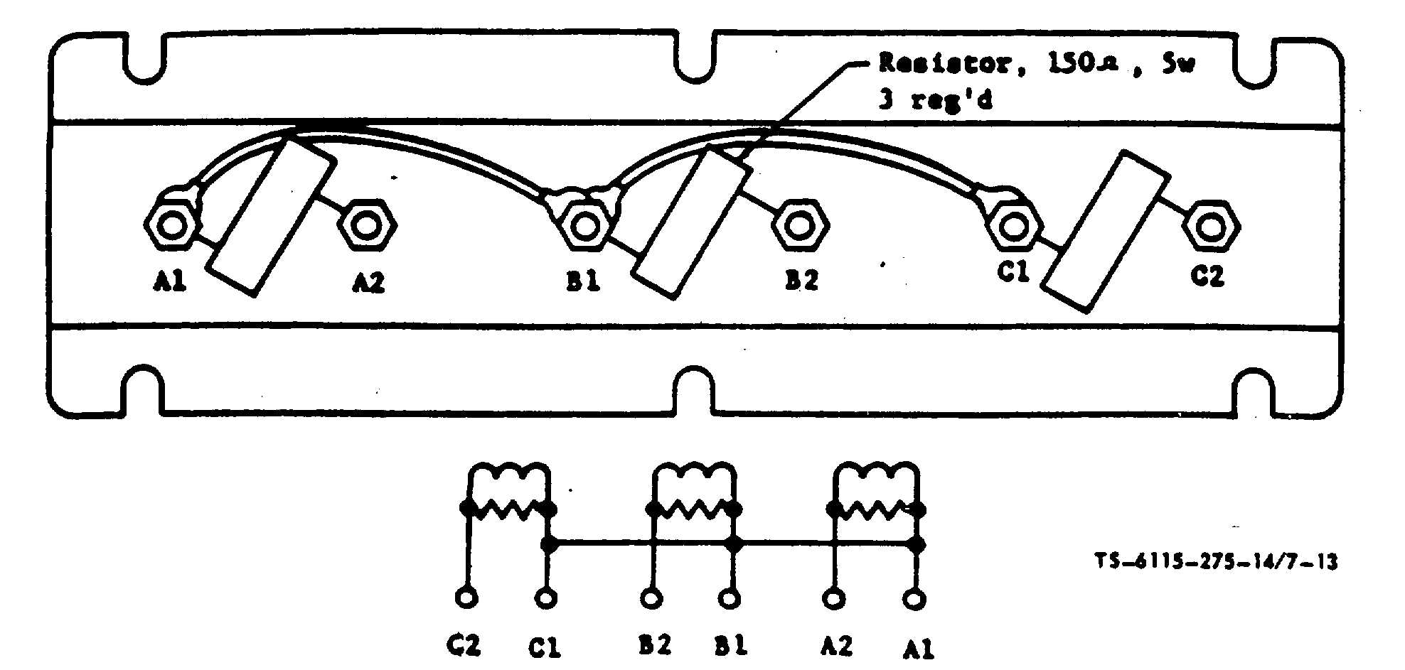
Figure 7-13. Current transformer, wiring diagram (Model MEP-018A).
7-11.
Current Transformer
a.
Removal. Refer to figure 7-1 or 7-2 and
remove the current transformer
from
the
applicable
model
generator set.
b.
Cleaning, Inspection, and Repair.
(1)
Clean with a clean, dry cloth.
(2)
Inspect for corrosion and damage.
Replace a damaged transformer.
c.
Testing (Model MEP-018A).
(1)
Refer to figure 7-13. Disconnect
and
test
resistors
with
a
multimeter. Proper resistance is
150 ohms + 1%.
(2)
Test transformer windings for
continuity. Replace defective
resistors or transformer.
d.
Testing (ModelMEP-023A). To test the
current transformer for continuity,
disconnect the six leads and
remove the three resistors from
the transformer.
Change 8 7-14.7


