
TM 5-6115-271-14
TO 35C2-3-386-1
TM-05926A-14
NAVFAC P-8-613-14
(b) Remove screws (2) and washers (3)
CAUTION
securing Q2 to housing.
Do not remove the white heat sink paste
(c) Pull transistor (1) straight from hous-
from the mica insulator, transistor, or regu-
ing, being careful not to damage the mica insulator
later housing. If this compound is removed
under the transistor.
transistor Q2 will overheat and become dam-
aged.
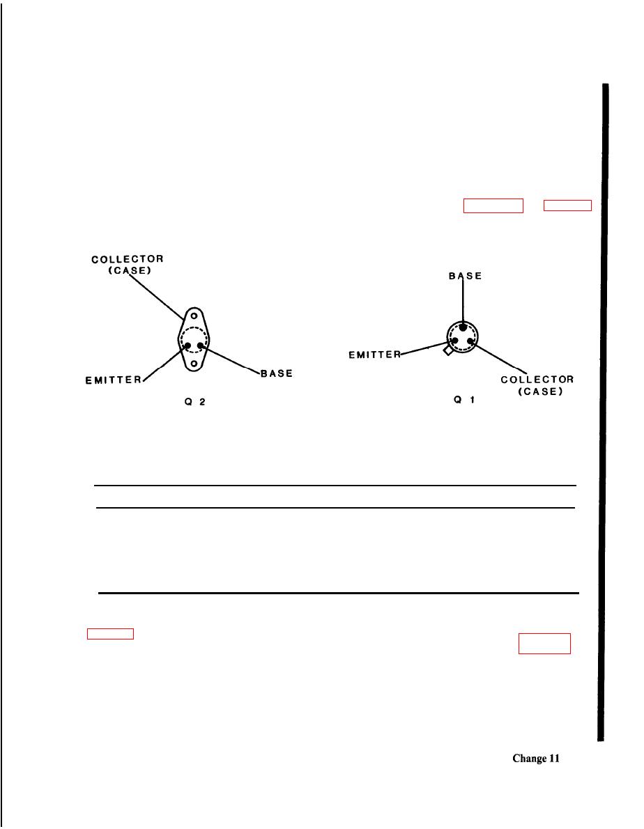
to read ohms). Refer to Figure 8-1A and Table 8-1.
Multimeter (+) and () refer to the multimeter test
leads.
Multimeter ( + )
Multimeter ( )
Meter Reading
Emitter
Infinite (oo)
Collector
Infinite (oo)
Base
Collector
Infinite (oo)
Emitter
Collector
Base
1 to 50 ohms
Collector
Emitter
1 to 50 ohms
Base
Base
Infinite (oo)
Emitter
(e) Readings other than those listed in
(3) Remove terminal strip TB1.
within Q2 and Q2 should be replaced.
that secure terminal strip TB1 (5).
NOTE
(b) Gently pull terminal strip TB1 (5)
Do not install transistor Q2 at this time.
along with the printed circuit board upward.
With Q2 removed, transistor Q1 can be
tested without removal of the transistor from
the printed circuit board.
