TM 5-6115-323-14
(5) Generator assembly, DC unit.
Type
............................
.
DC, brushless, self-excited
Frequency..................... DC
Speed ..................... 3600 rpm
Temperature rise .........
75°C.(1670F.)
Power ...........................
1.5 KW
Voltage.............................
28VDC
Current ............................ 53.5 amperes
Duty............................
Continuou
s
Altitude rating ..................... 1.5
KW level to 8,000 ft.
(2,400 m))
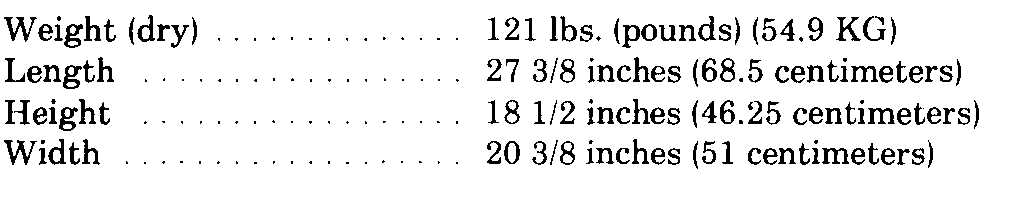
e. Dimensions and Weight, AC and DC Units
(figs. 1-2 and 1-4).
f. Generator Repair and Replacement Standard.
(1) Alternator rotor.
Resistance of connected 15.5 ohms ± 5% windings at 77°F. (25 °C.)
(2) Exciter rotor.
Resistance between lead 5.84 ohms ± 10% pairs at 77°F. (25 °C.)
(3) AC unit alternator stator.
Resistance between lead 1.32 ohms ± 10% pairs (T1-T2 and T3-T4)
at 77°F. (25°C. )
(4) DC unit alternator stator.
Resistance between lead -0.031 ohms ±20% pairs (T1l-T12,
T12-T13, T-14-T15, T15-T1l) at 77°F, (25°C.)
(5) Excitation windings.
Resistance (T1-T2) at 8.2 ohms ± 10% (77°F. (25°C. ))
(6) Exciter stator.
Resistance of winding at 215 ohms ± 10% 77°F. (25°C.)
(7) Voltage regulator.
Winding resistance at 77°F. (25°C. )
Coil C1A-C2B
36 ohms ± 10%
Coil C2A-C2B
12.2 ohms ±10%
Coil C3A-C3B
36 ohms ± 10%
Voltage Operating Range
AC
DC
Minimum range from no
110 to 130 V
23-36 V
load to rated load,
225 to 255 V
ambient temp.
At extreme temperatures
120V±5%
28 V ± 4%
-65°F. (-54°C.) and
220 v ± 5%
125°F. (52°C. )
Regulation
No load to rated load and
120 v ± 4%
28 V ± 4%
rated load to no load
220 v ± 5%
Steady State Regulation
AC
At constant load from no
120 v ± 170
28 V ± 1%
load to rated load
220 V ± 1%
g. Generator Assembly Nut and Bolt Torque Data.
Generator-to-adapter plate
screws
8 to 10 ft. lbs.
Through stud
16 to 18 ft. lbs.
Baffle-to-generator screws
8 to 10 ft. lbs,
Rectifiers
20 to 25 ft. Ibs.
h. Wiring Diagrams. Figures 1-5 and 1-6 show the
wiring diagrams that are applicable to the generator
sets.
i. Schematic Diagrams. Figures 1-7 and 1-8 show
the schematic diagrams that are applicable to the
generator sets.
1-11.
Differences Between Models
The differences between the Model MEP-015A (AC
Unit) and the Model MEP-025A (DC Unit) are minor
differences in the design of the control box, a change
in the windings of the stator, and the addition of rec-
tifiers and heat sinks in the DC generator. Where dif-
ferences exist, each model is covered separately in the
applicable maintenance sections of this manual.
1-8
Change 5