TM 5-6115-434-12
c.
Test (fig. 8-10).
(1)
Place atomizer assembly in a suitable holding device and connect a source of filtered fuel to the atomizer
inlet. Provide a suitable container for catching fuel spray from atomizer discharge.
(2)
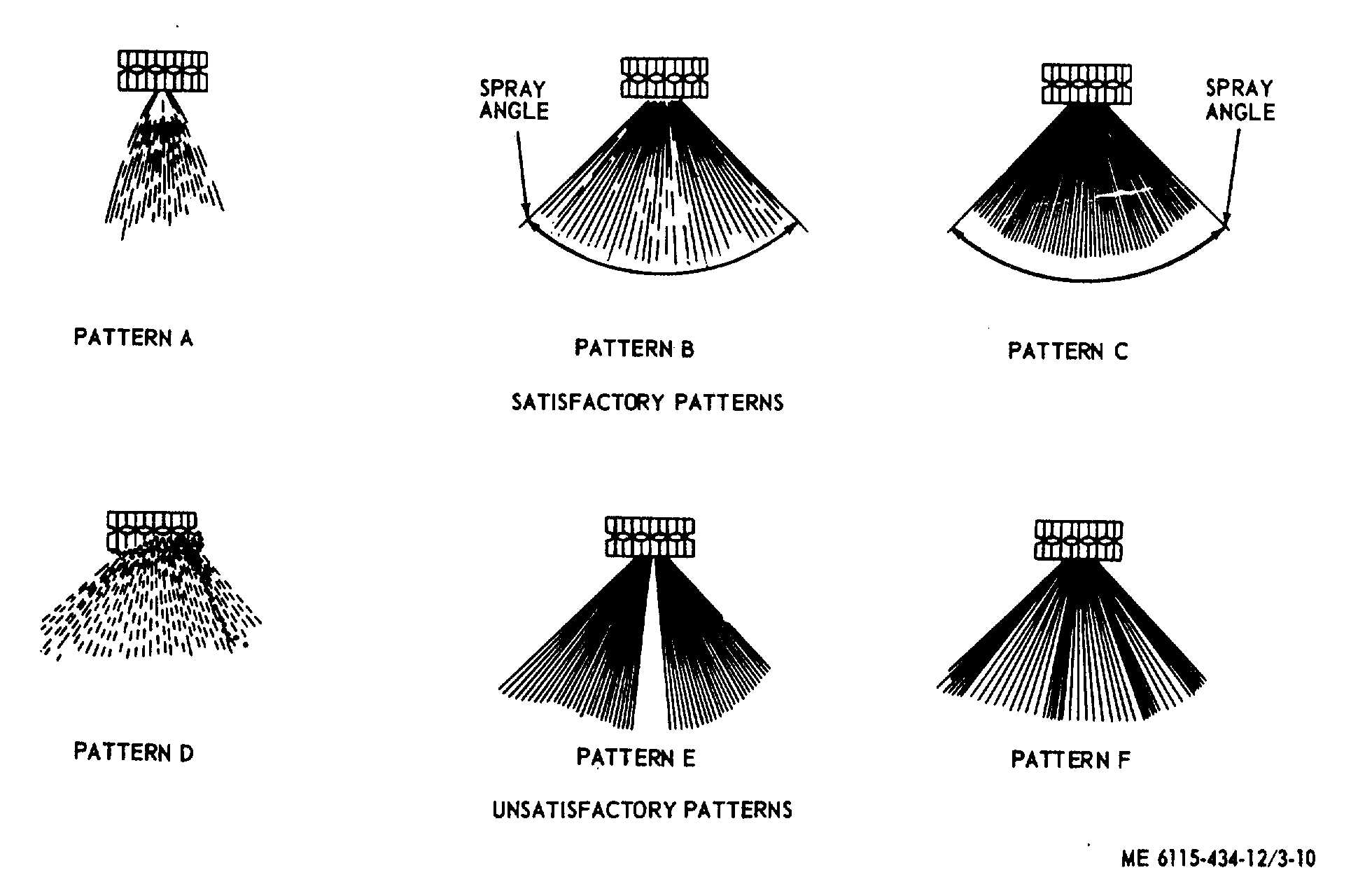
Apply fuel' at an inlet pressure of 10 1 psig and observe that the spray pattern is approximately as shown
on pattern A. There shall be no fizzing or bubbling back over atomizer assembly nut. (pattern D) No solid jets of fuel
shall be permitted. (pattern F) No discontinuities in spray pattern shall be permitted. (pattern E).
(3)
Increase fuel pressure to 25 1 psig inlet pressure and observe that the spray pattern is conical in shape,
steady and even; approximately as shown in pattern B. No solid jets of fuel shall be permitted (pattern F) nor shall
discontinuities in spray pattern be permitted (pattern E). Included angle of spray pattern, at a 6
±
1 inch radius from
atomizer assembly orifice shall be approximately 75 to 95 degrees.
(4)
Increase fuel pressure to 200 ±
2 psig inlet pressure and observe that the spray pattern is conical in shape,
steady and even; approximately as shown in pattern C. No solid jets of fuel shall be permitted (pattern F) nor shall
discontinuities in spray pattern be permitted (pattern E). Included angle of spray pattern at a 6 1 inch radius from
atomizer assembly orifice shall be approximately 75 to 95 degrees.
(5)
Upon completion of the spray pattern test, shut off valve supply to atomizer assembly. Disconnect line to
inlet and remove assembly from holding device.
Figure 3-10. Fuel atomizer assembly spray test patter.
3-41