TM 5-6115-329-14
TO 35C2-3-440-1
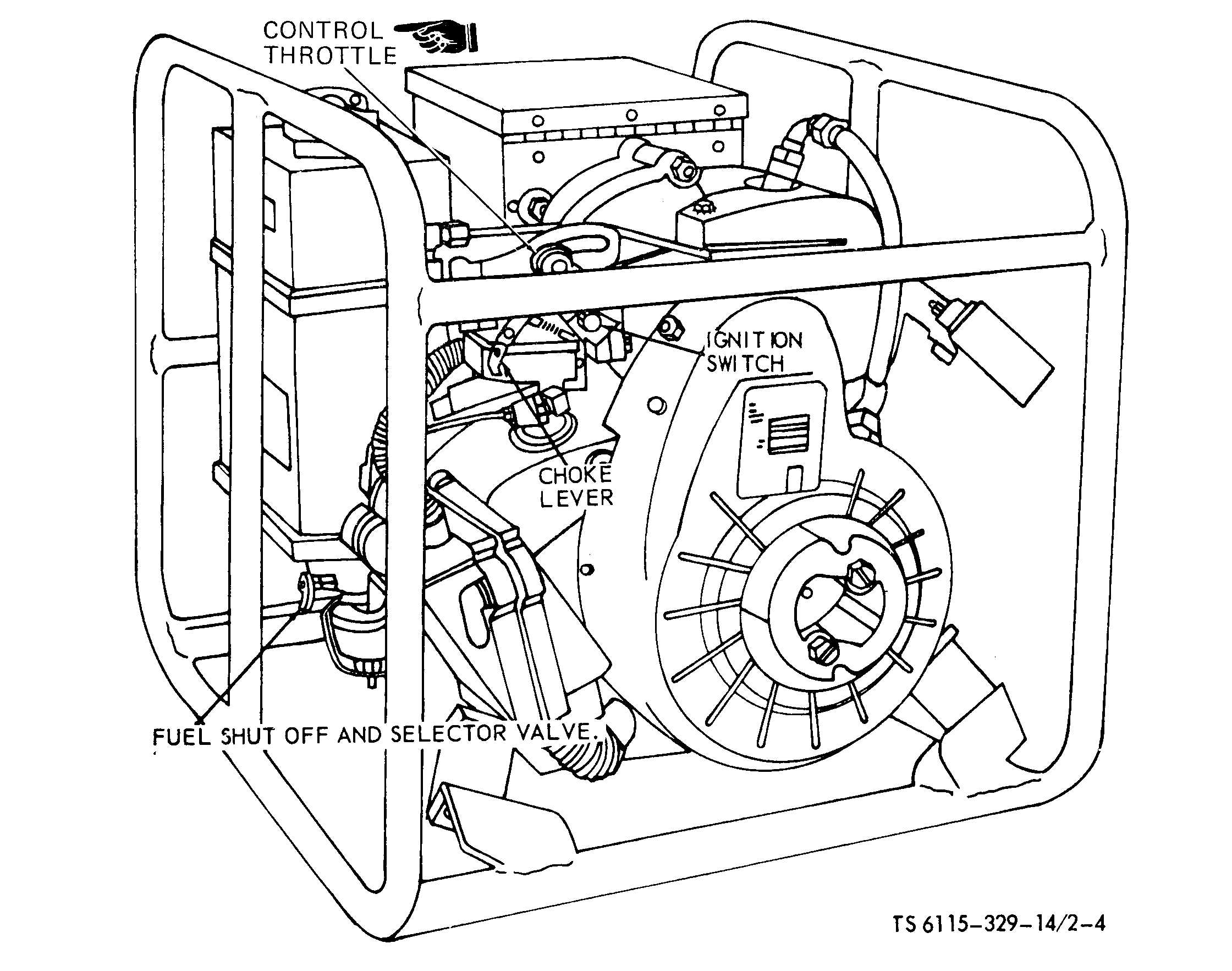
Figure 2-4. Engine controls.
(8) On model MEP-019A only, place LOAD ON-
OFF-FLASH switch in FLASH position. When
engine has attained rated speed, observe panel
meter for a voltage indication. Release switch when
voltage reaches a minimum value of 100 volts.
(9) If generator output voltage on model MEP-
019A fails to develop after set has attained rated
speed, and the LOAD ON-OFF-FLASH switch has
been placed in FLASH position, field flashing from
an external source will be required. The field is
flashed by momentarily connecting a 12-volt DC
source (with resistor of 20 ohms, 5 watts connected
in series) to terminals 8 and 7 of TB 2 (fig. 1-8). Ter-
minal 8 is positive with respect to terminal 7. The
series resistor may be omitted if voltage polarity is
strictly observed.
CAUTION
Reversing field flashing polarity
from that indicated above will result
in the destruction of the voltage
regulator, rendering the set inopera-
tive.
e. Stopping.
(1) Position LOAD ON/OFF switch (models
MEP-014A and Mep-024A), or LOAD ON-OFF-
FLASH switch (model MEP-019A) in OFF position
(fig. 2-1,2-2 and 2-3).
(2) Turn the voltage rheostat fully counterclock-
wise.
(3) Run the engine at rated speed for 3-5 minutes
to cool down the set.
(4) Place ignition switch in OFF position (fig. 2-4).
Change 1
2-5